
Before you start
- Order material corresponding to the BOM and amount of modules. If you order at Aliexpress from Europe, you will need to wait a few weeks for your parts if you choose the cheapest shipping method. Consider that!
Instructions for modules/unit
- Print plastic parts (in order to check dimensions & tolerances, you should produce only one piece each. Perform a functional test with the module. If everything works fine, print the rest)
- Rework parts, e.g. screw holes (if necessary)
- Mounting procedure module/unit
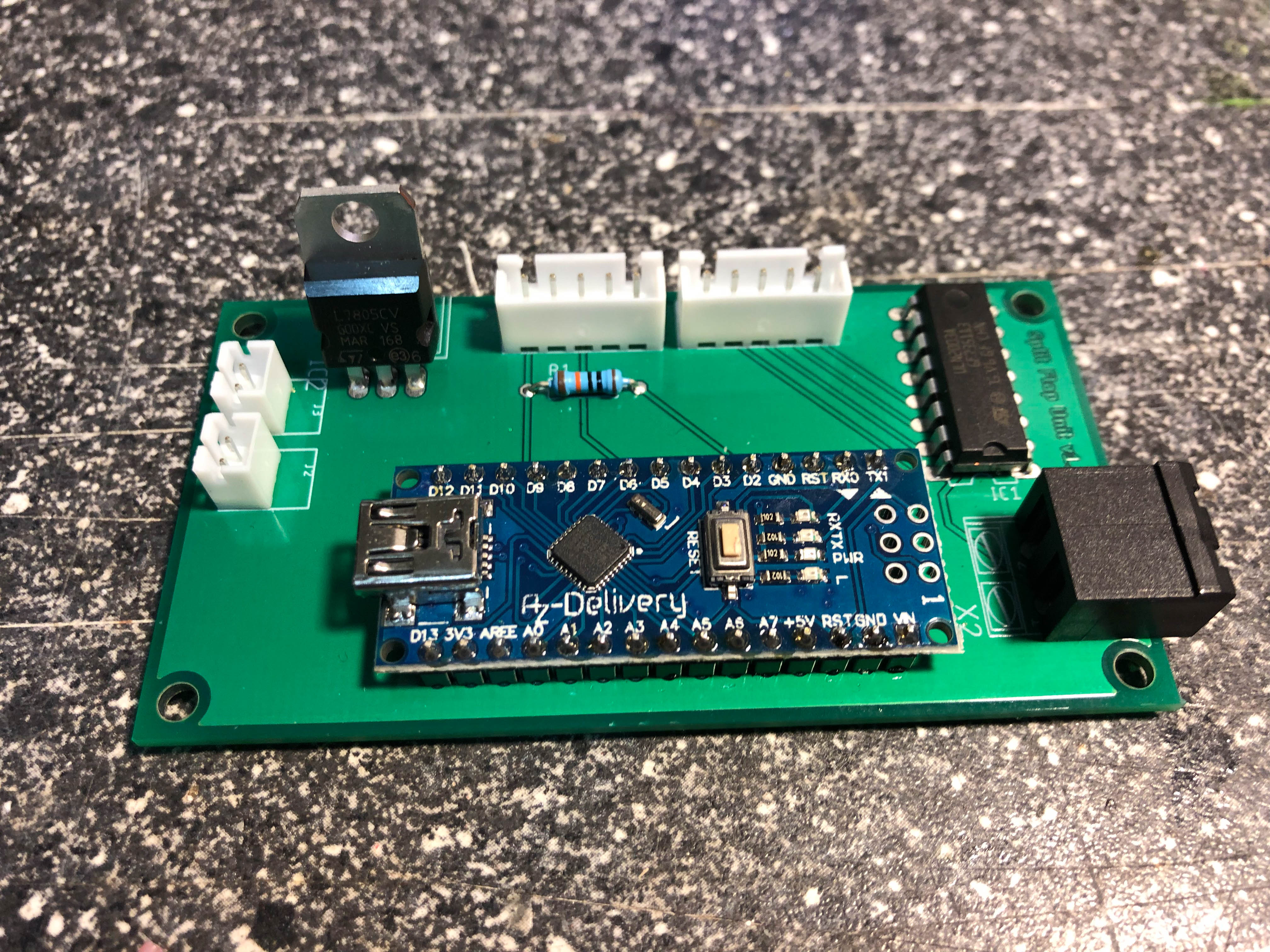
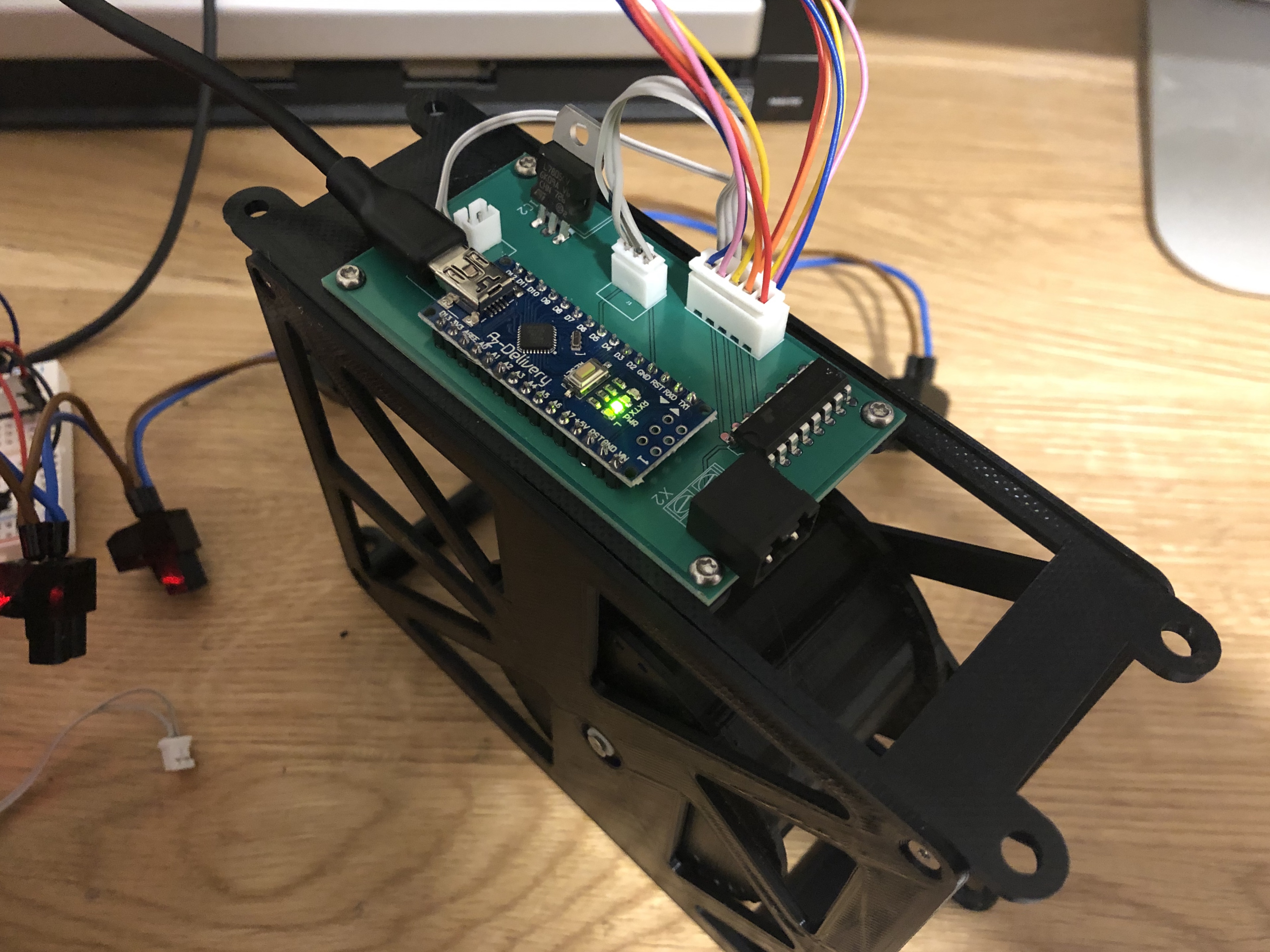
- Solder unit PCBA
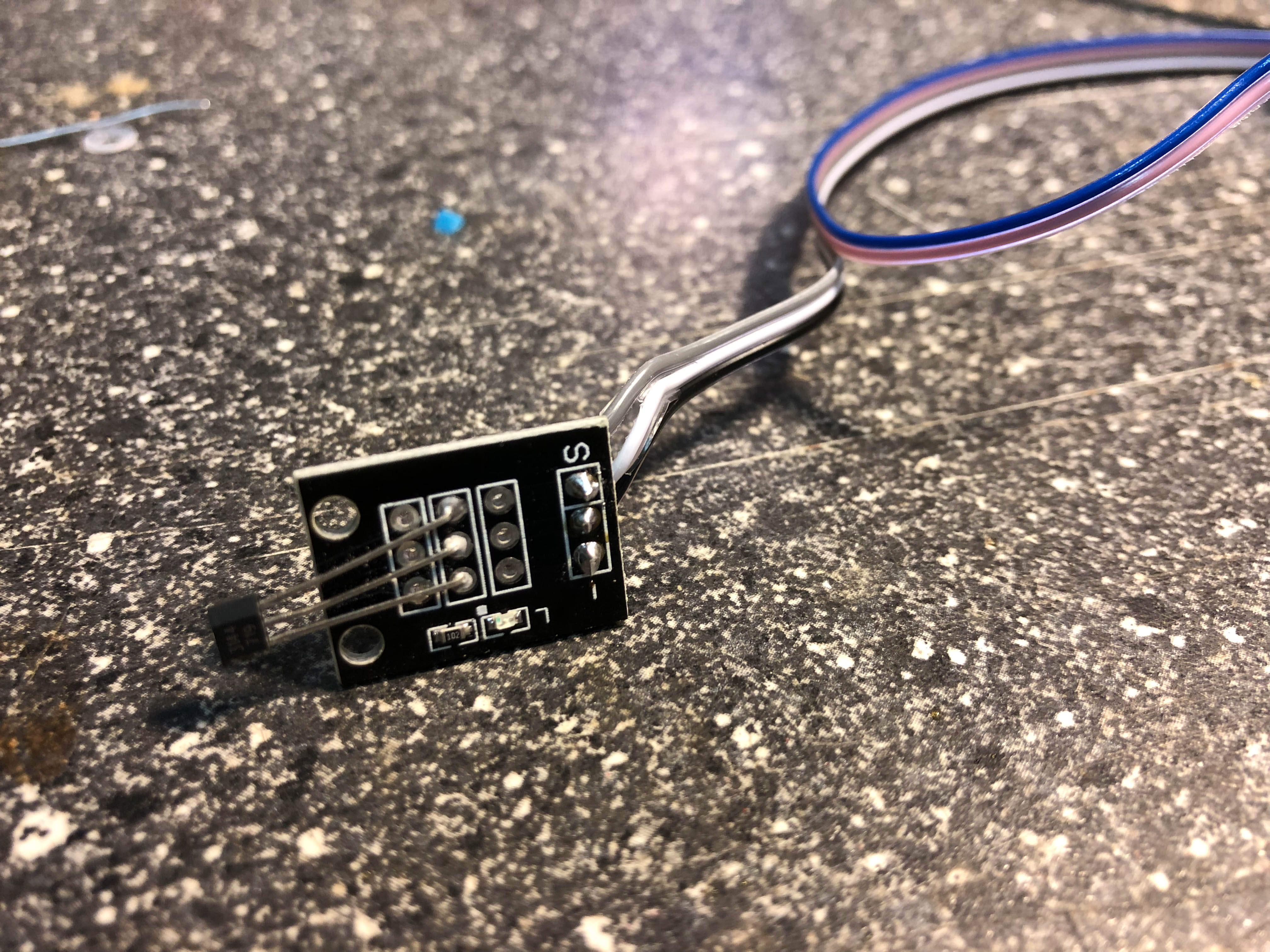
- Remove connector pins from KY-003 and solder cables (5 wire, 21cm long) with PCBA. Crimp JST XH crimps on the other side of the cable
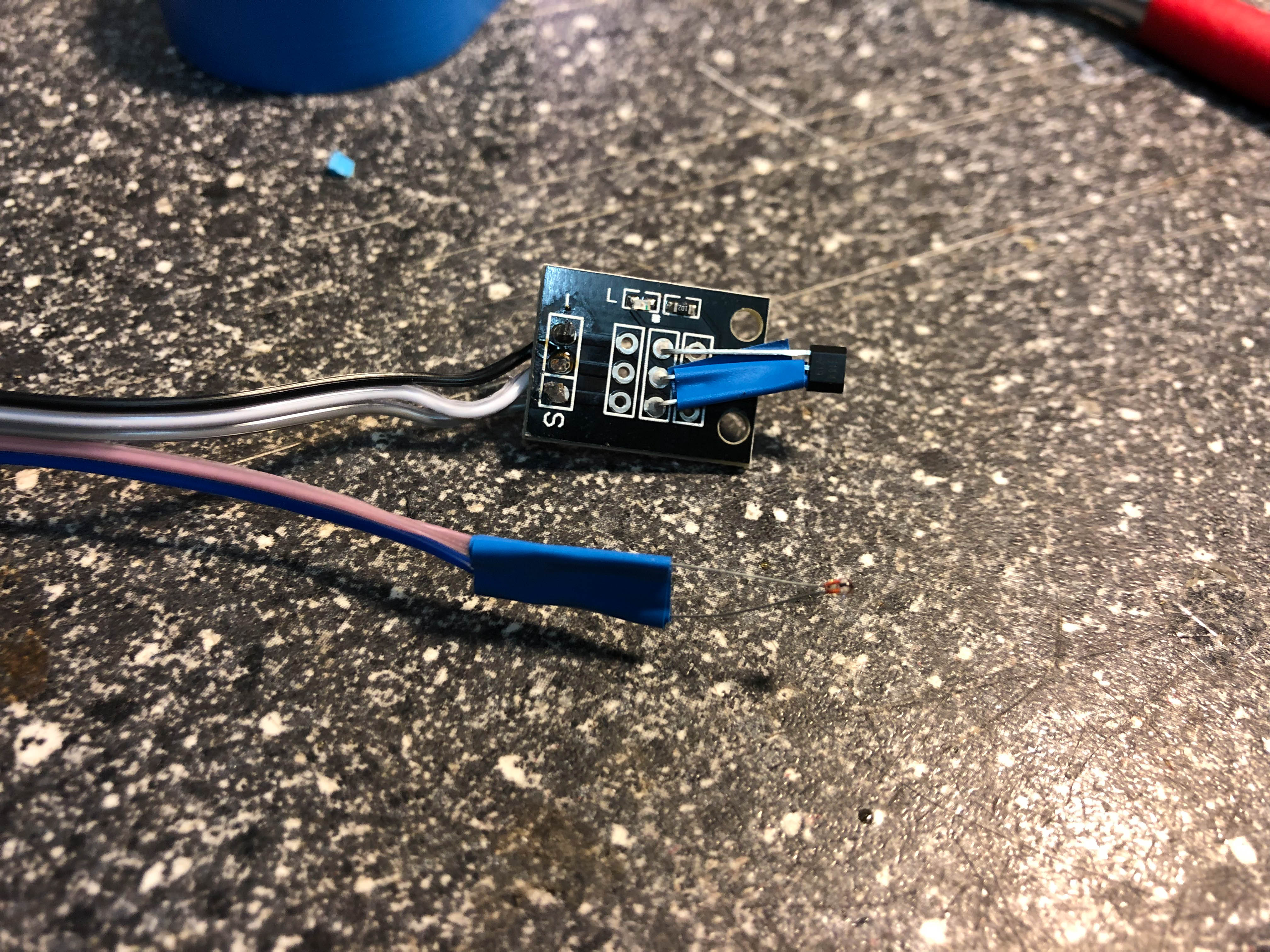
- Solder the thermistor on the two open wires
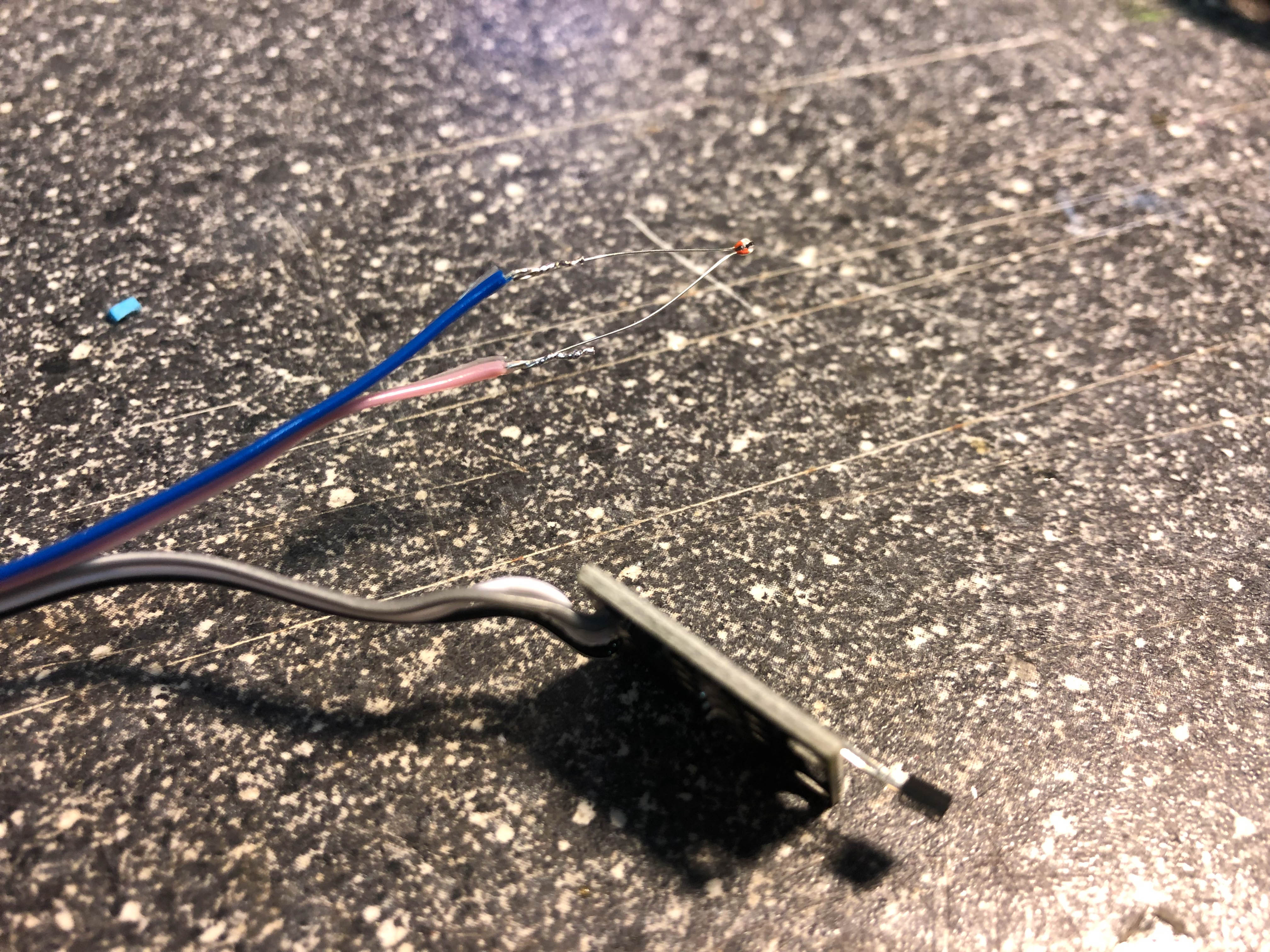
- Insulate the hall pins and the thermistor pins with some insulating tape
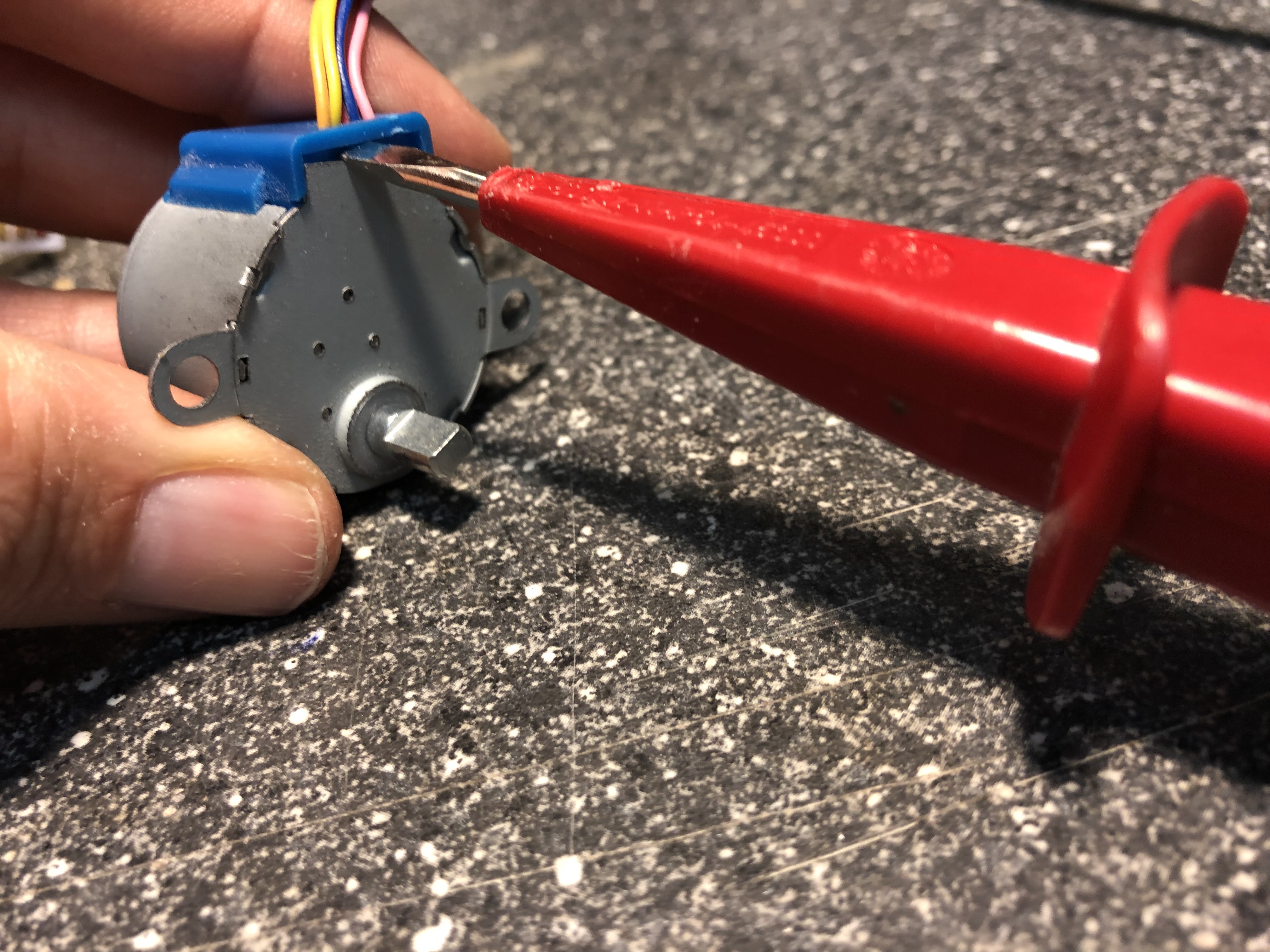
- Remove plastic clip from 28BYJ48 (we need the space ;-)) and screw the stepper on the motorblock
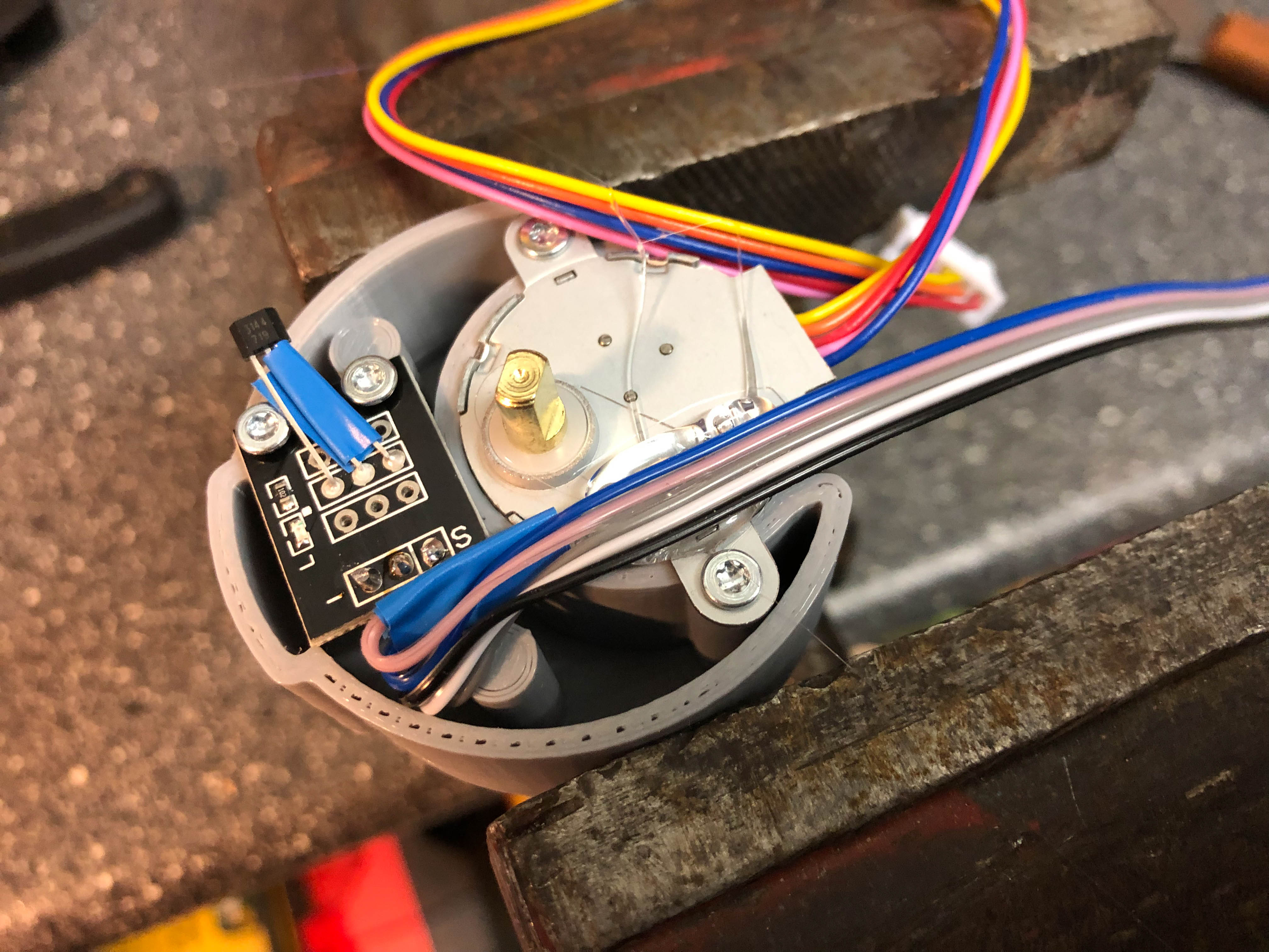
- Screw down KY-003 on motor block
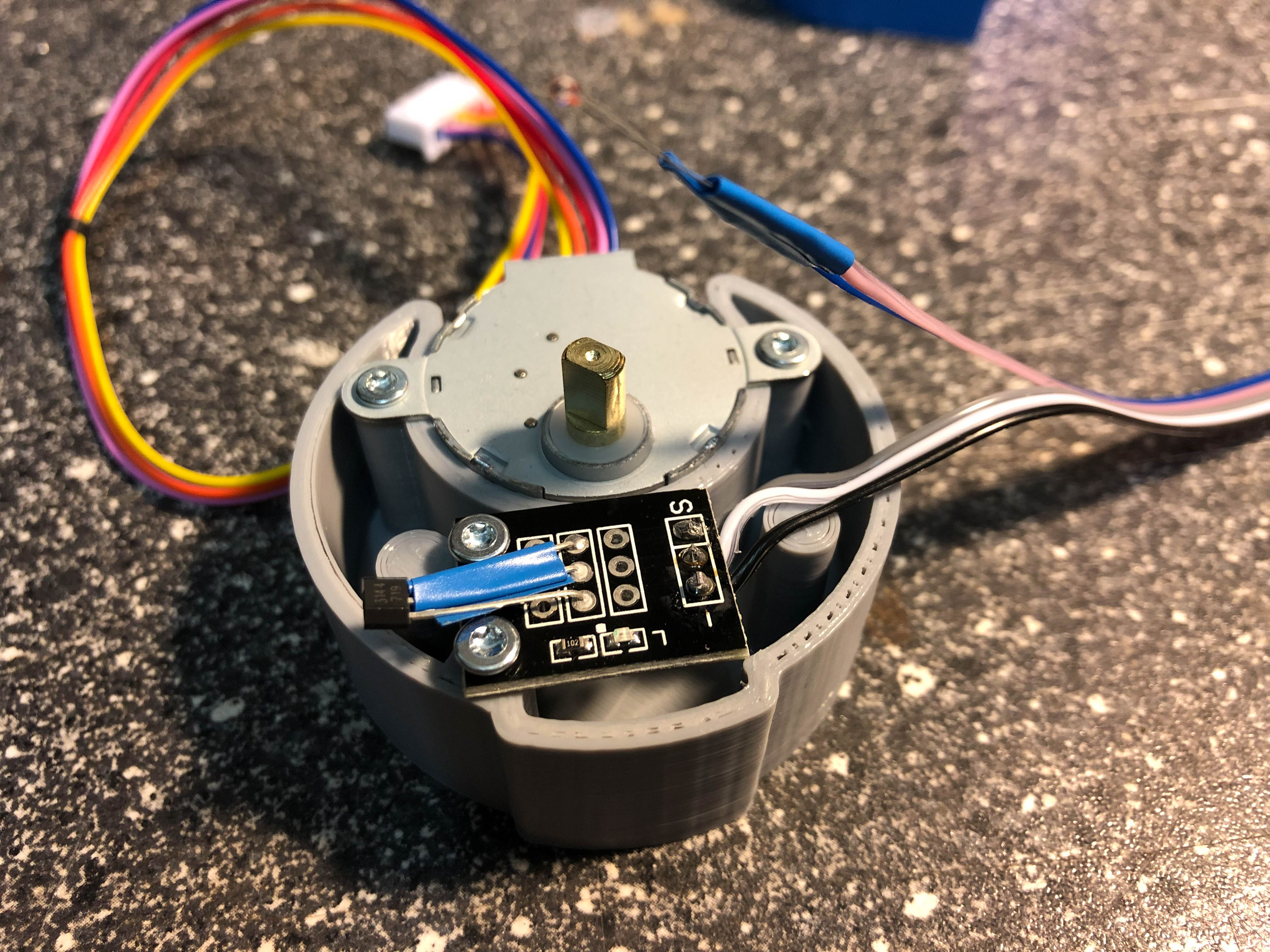
- Fix thermistor on stepper using some hotmelt
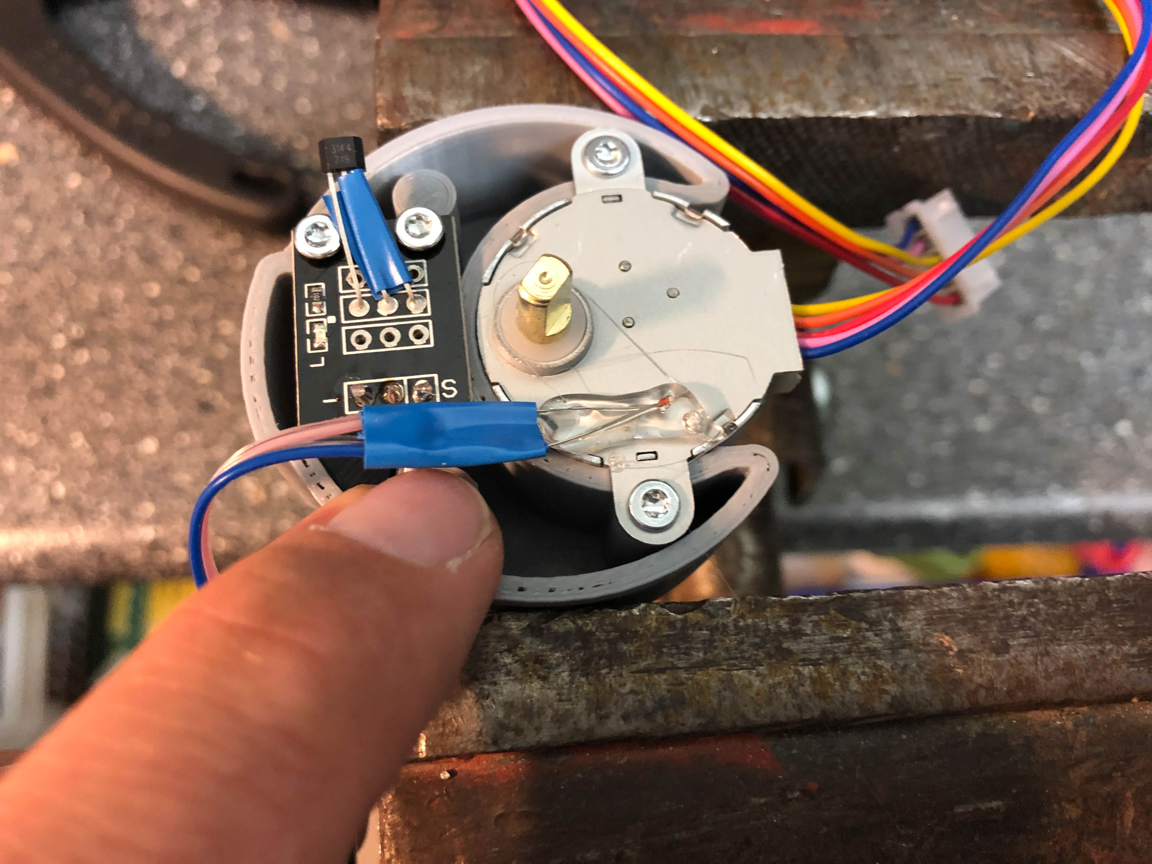
- Fix the cable on the thermistor using some more hotmelt
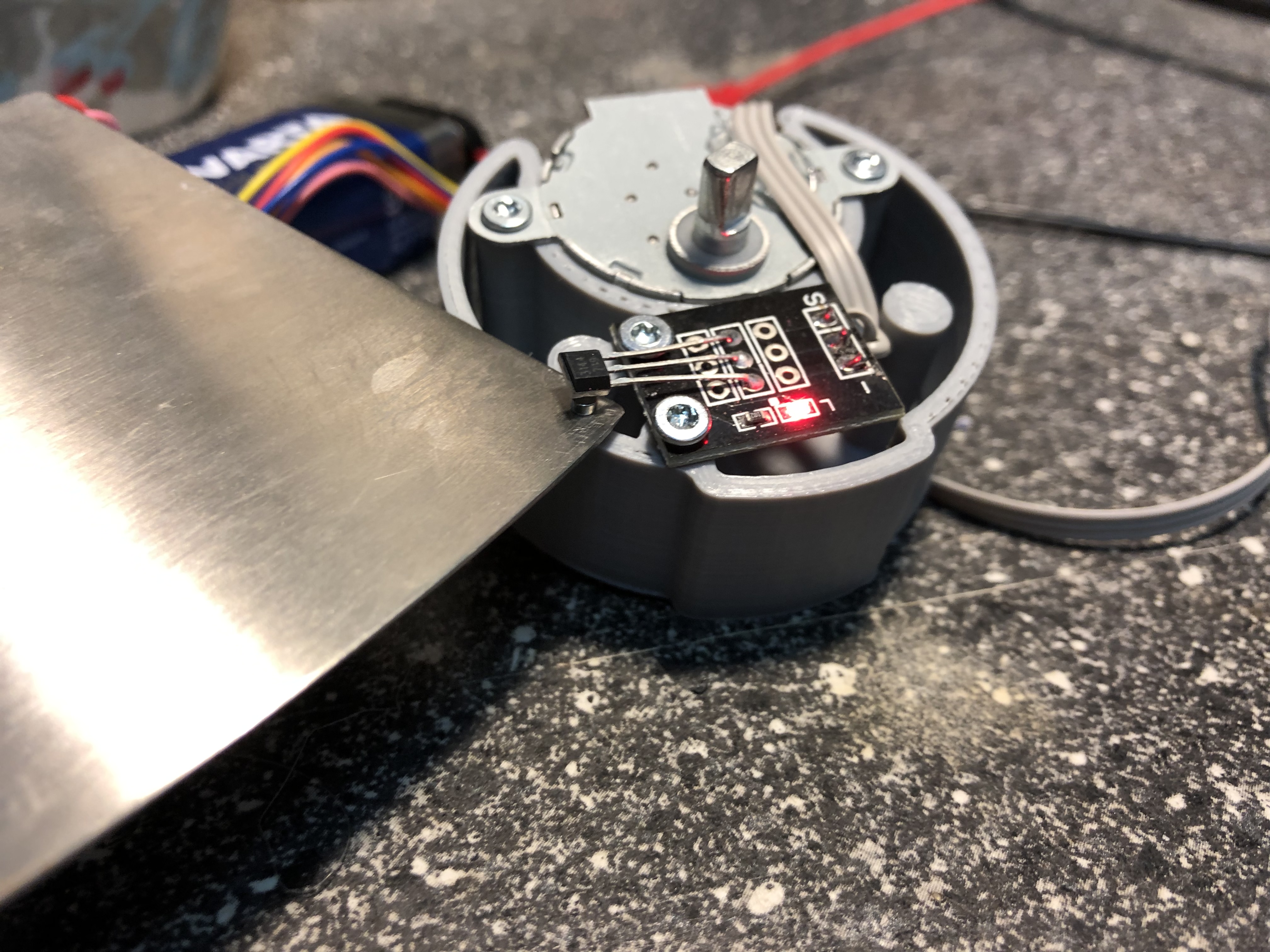
- Connect KY-003 temporary with a 9V battery. Put the 2mm magnet on a scraper and move it below the head of KY-003. The LED should lighten up. If not, rotate the magnet top side down on the scraper and test again. If passed, the magnet is oriented correct to put it into the revolver.
- Press the magnet inside the small hole of the left revolver part
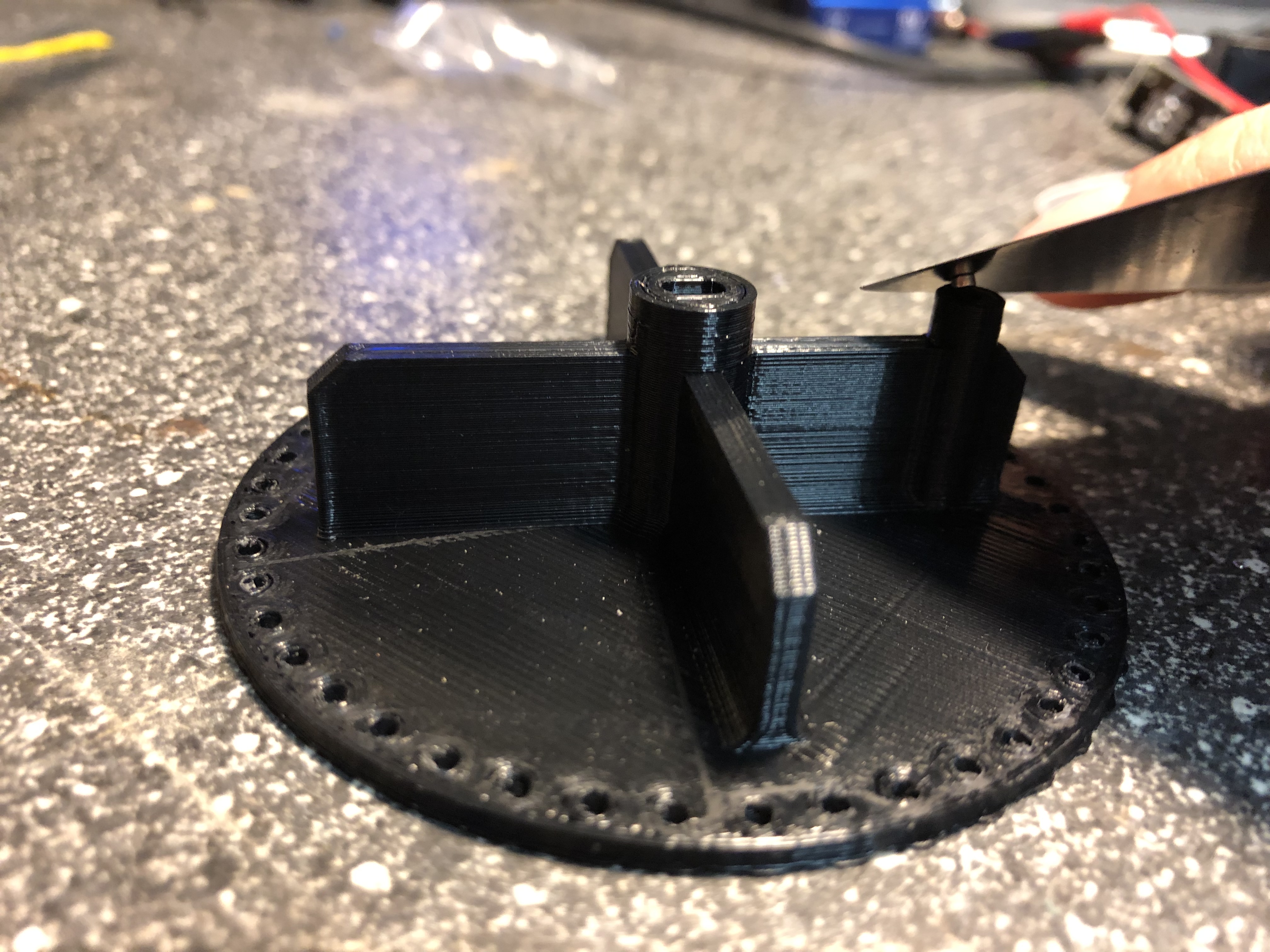
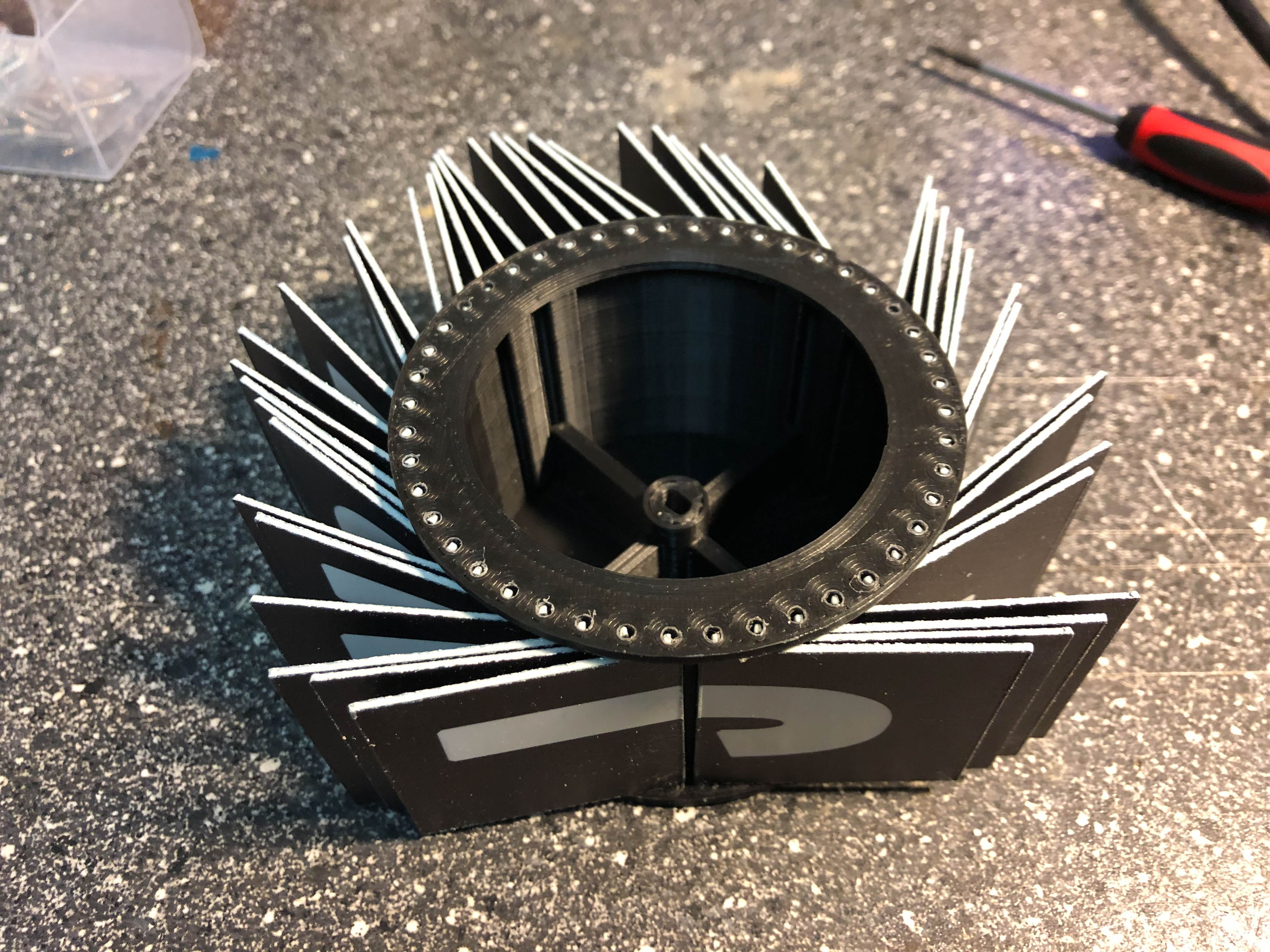
- Clip both revolver sides together. Take care that the small marker on the outer diameter in aligned together. Put the flaps on the revolver by bending very carefully
- Put the motorblock into the revolver. Take care that the revolver is aligned to the coding of the axle. Screw the right housing part onto the motorblock

- Screw the front housing on the right side housing

- Screw the rear housing on the right side housing
- Put one washer on a screw, put the screw into the center hole of the left side housing. Put another two washers from the inner side of the housing on the screw and screw it into the revolver center hole. Screw the housing left side with another four screws to the front and the rear housing.

- Screw the PCBA on the rear housing with the shorter screws
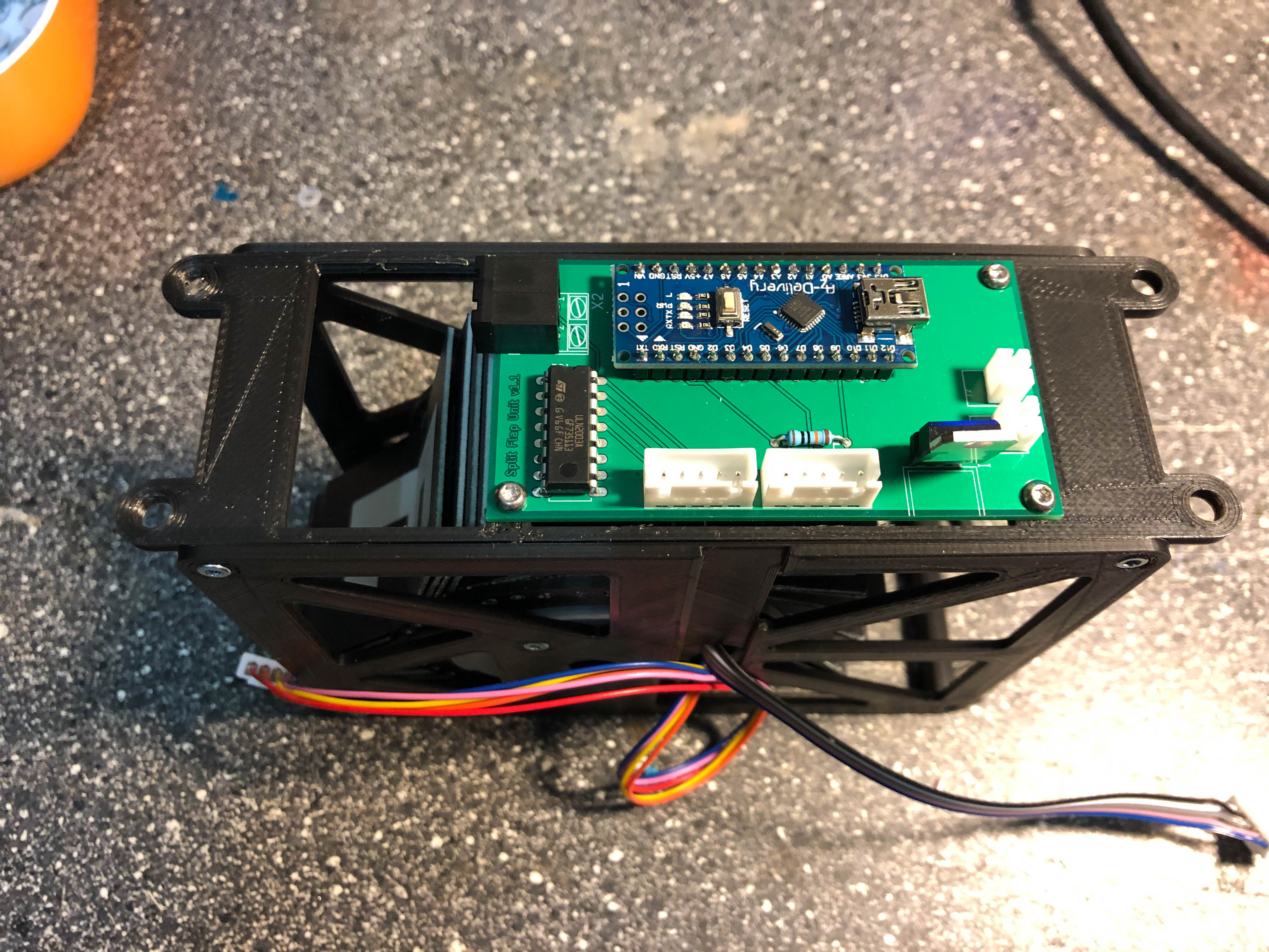
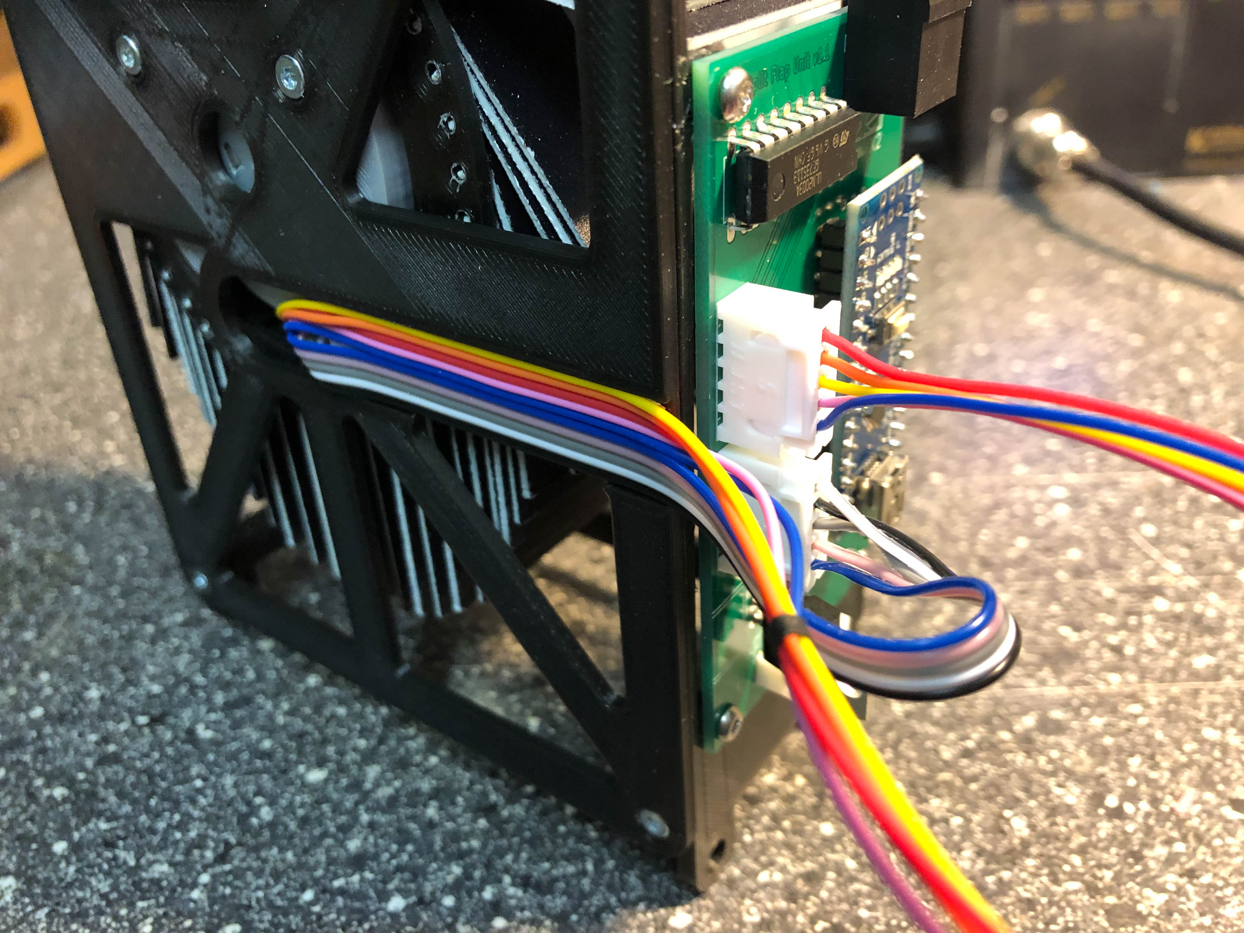
- Put some double faced adhensive tape on the cable slot and put the cables on the adhesive
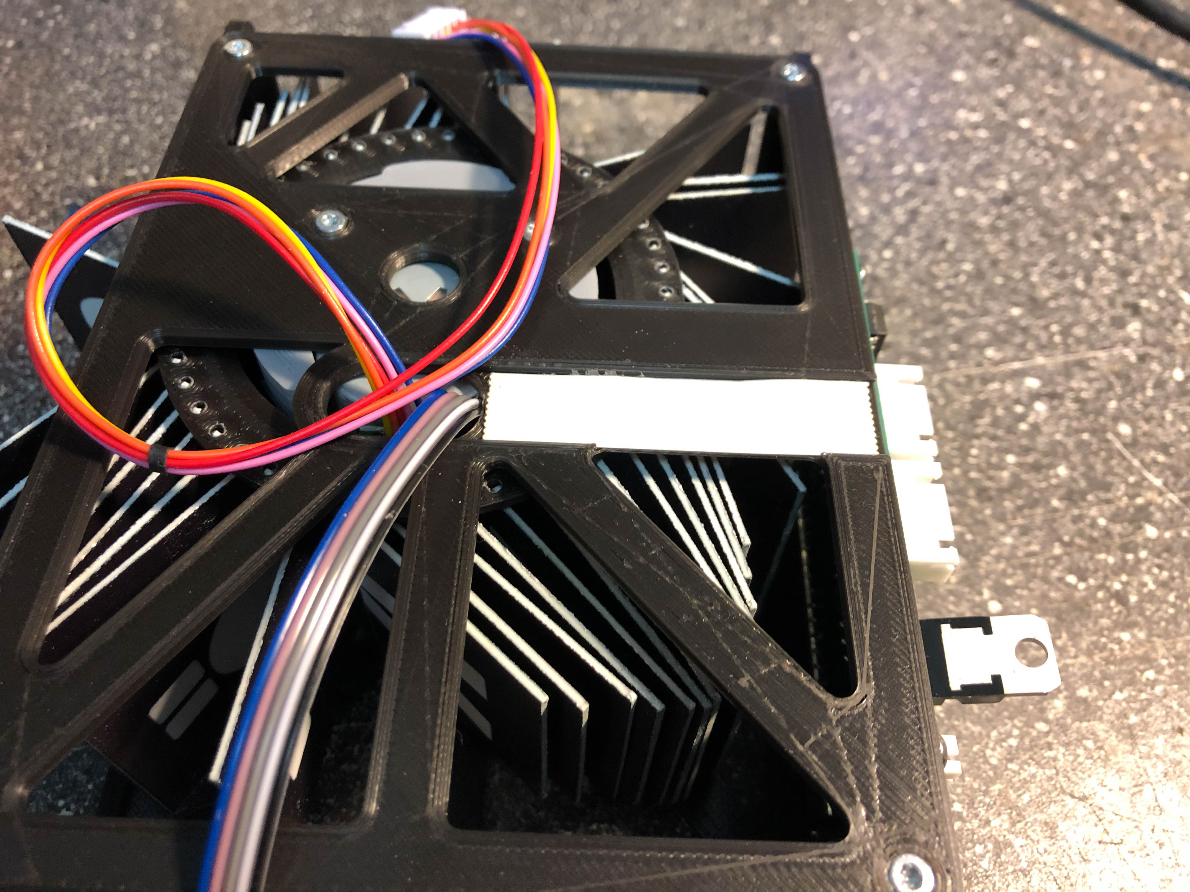
- Connect the plugs to the PCBA
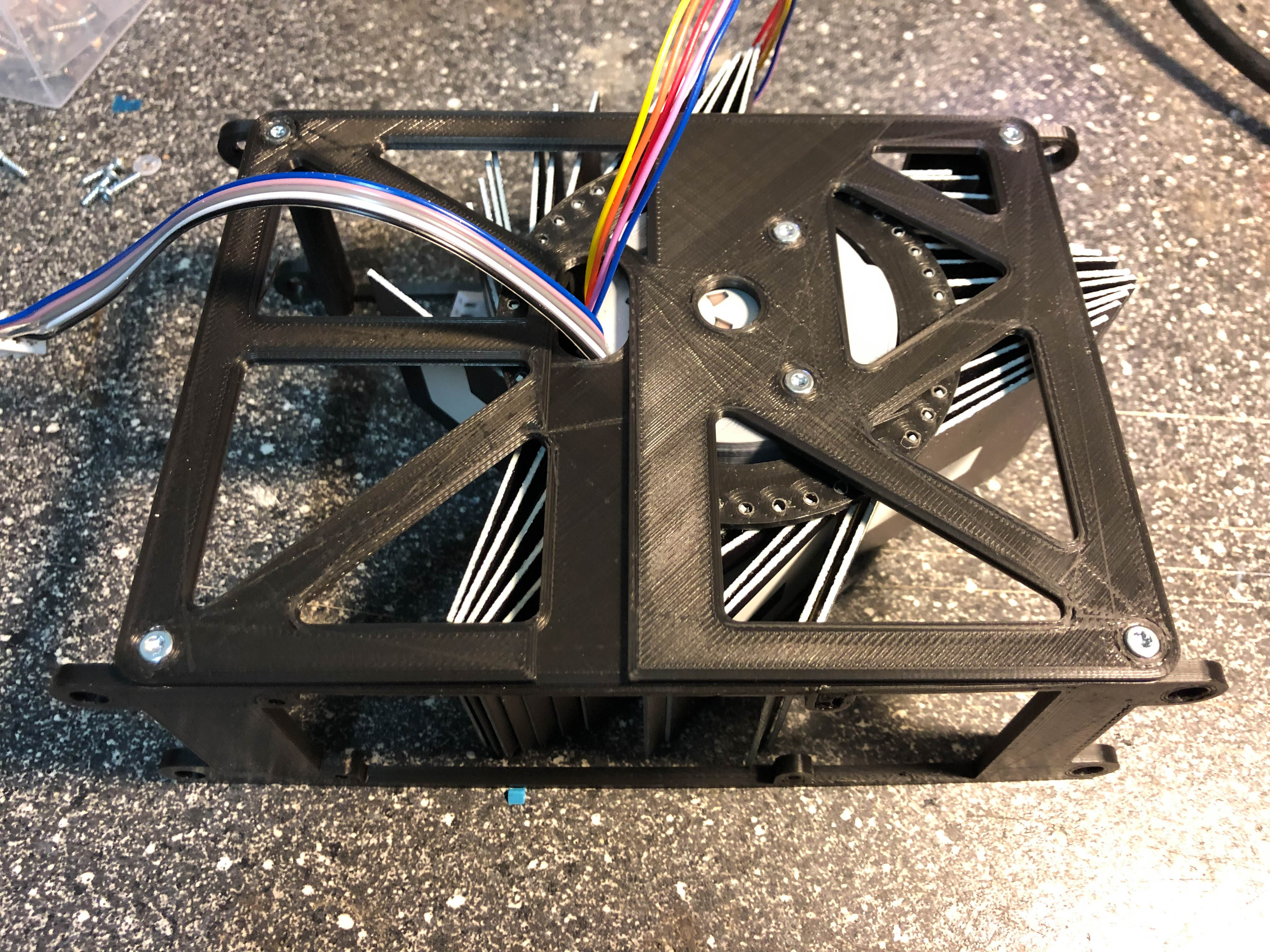
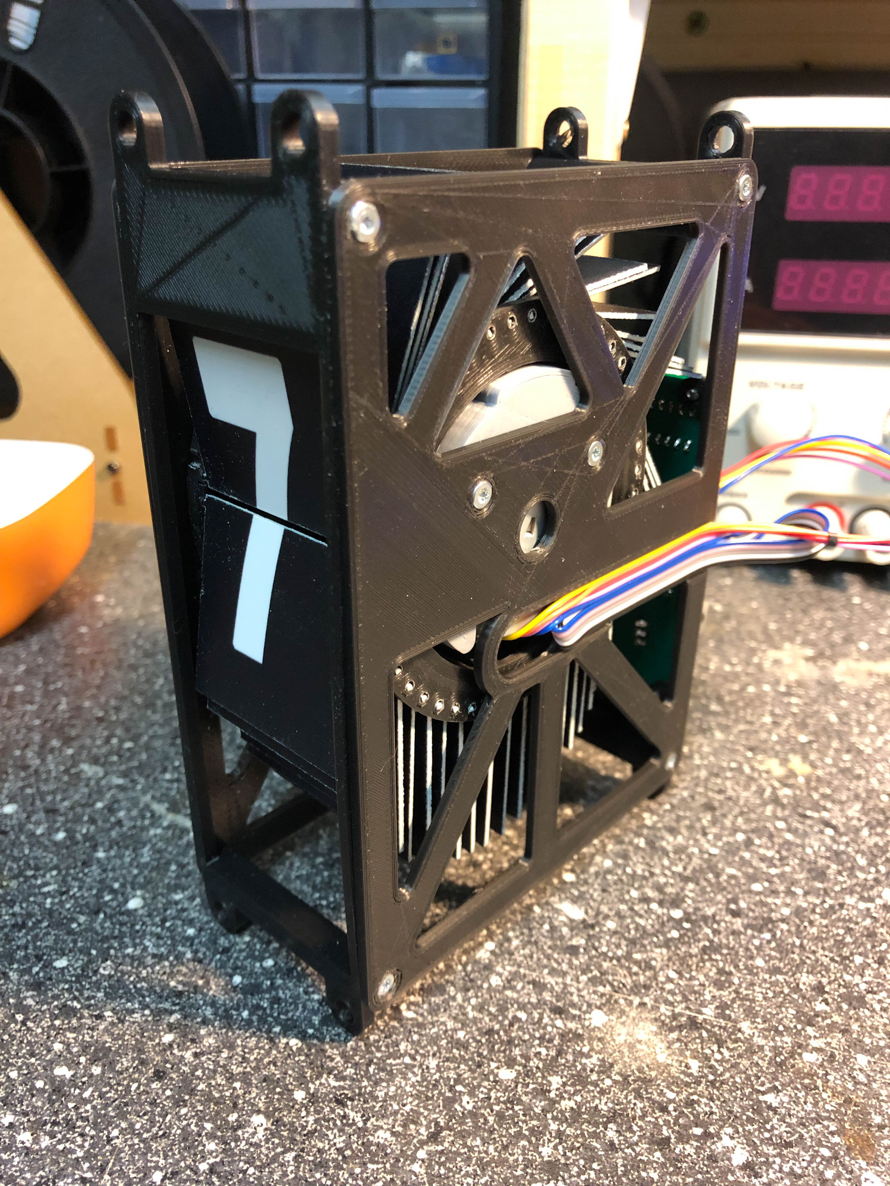
- Your first unit is mounted 😉
- Flash Arduino
- Open split_flap_unit in your IDE (e.g. Visual-Studio Code, Arduino IDE,…)
- Change i2c address (starting with 1 for 1st unit, 2 for 2nd unit,…)
- Change CALOFFSET to 0
- Connect unit with computer and flash unit
- Take a look of the rotation of the revolver. From the front view, the revolver should move down. If not, you have to change rotationDirection from -1 to 1 or from 1 to -1 (there are some 28BYJ48 which operates in opposite direction)
- Open serial monitor. Check if you have an calibration error. If not, the revolver is now in zero position. If you have an calibration error, the sensor head of the KY-003 might be too far away from the magnet. Correct that and try again
- Increase CALOFFSET if the revolver doesn’t show a space (blank flap). You may need to adapt this value if wrong letters are displayed.
- Congratulation, you have finished your first module!
Instructions for master
- Change baudrate of ESP8266/01. In my case the communication with the default baudrate of 115k didn’t work proper (transmission errors), so I set the the default baudrate to 9600. Link for instructions: https://splitflap.home.blog/troubles/
- Solder the PCBA
- Flash master
- Open split_flap_master in your IDE (e.g. Arduino IDE)
- Download needed libraries listed under libs
- Insert the SSID of your Wifi into ssid[]
- Insert your Wifi WPA/WPA2 password into pass[]
- Define a token for UDP transmissions messageToken
- Adapt I2C address array of connected units under displayUnits[], e.g. {8,9,10} if you have three connected units with I2C addresses 8, 9 and 10.
- Flash the device
- Open your serial monitor and check if the master is connected to your Wifi
- Connect the I2C bus of your master and your units
Instructions for flaps
The flaps can be produced in several ways. My preferred way was to let a PP plate (dimensions 1m x 1m) printed on both side by a supplier and cut the flaps using a laser cutter. Another option is to print the flaps and label the flaps using letter sticker. If you have a 2-component printer, you can print the flap and label them in one step. There are many other ways to build the flaps. Be creative 😉
